While I was waiting for my weekly chicken roast to cook, I had this really bad idea for a challenge. how much riscv verilog i can write from scratch in the next 2 hours until the chicken is done?
So, yeah that’s what I did on the last day of new year vacation.
2 hours to V hours Link to heading
I thought to start with a skeleton for single-cycle (See [H and H][1]) and try to build the blocks bottom up style.
At the 2 hour mark(minus the chicken prep time), I wrote
- Basic small blocks.
- Loaded make-shift hex.
- Spent 20 minutes to make VCD work with iverilog(I want that time back)
Not bad but it was obvious I failed the 2-hour challenge. So, I changed it to 5 hours instead. It seemed like a lucky number :)
Basic blocks Link to heading
- RAM
module ram #(parameter WIDTH=32, parameter ADDR=32) (
	input wire clk,
	input wire we,
    input wire [ WIDTH - 1: 0] din,
    input wire [ADDR-1 : 0] addr,
    output wire [ WIDTH - 1: 0] dout
);
	reg [WIDTH-1:0] mem [ 100 : 0];

	assign dout = mem[addr];


	always @(posedge clk) 	begin
		if (we) begin
			$display("%t Writing ram[0x%0x]=0x%0x", $time, addr, din);
			mem[addr] = din;
		end
	end
endmodule
- ROM
module rom #(parameter WIDTH=32, parameter ADDR=32) (
    input  wire [ADDR  - 1 : 0] addr,
    output wire [WIDTH - 1 : 0] dout
);

	reg [WIDTH-1:0] mem [ 100 : 0];

	assign dout = mem[addr];
endmodule
- Register file
module regfile#(parameter WIDTH=32) (
	input clk,
	input [4:0] addr1,
	output [31:0] dout1,

	input [4:0] addr2,
	output [31:0] dout2,

	input [4:0] addr3,
	input [31:0] din3,
	input we3
);
	reg [WIDTH-1:0] mem [0:31] ;

	// x0 is zero
	assign dout1 = addr1 == 0 ? 5'b00000: mem[addr1];
	assign dout2 = addr2 == 0 ? 5'b00000: mem[addr2];

	always @(posedge clk) begin
		// Don't write to x0
		if (we3 && (addr3 != 5'b00000)) begin
			$display("%t Writing regfile[%0d]=0x%0x", $time, addr3, din3);
			mem[addr3] <= din3;
		end
	end

endmodule
- ALU(add only)
Data-path and control unit Link to heading
I started with LW datapath then control to pipe-clean the connection all the way to memory and back to regfile and I used the usual stages:
- Fetch
- Decode
- Execute
- Write-back
LW and SW follow similar format except the immediate. So, Decoding was not that hard
        assign opcode   = instr[`OP_RANGE];
        assign funct3   = instr[`FUNCT3_RANGE];
        assign rf1              = instr[`RS1_RANGE];
        assign rf2              = instr[`RS2_RANGE];
        assign rf3              = instr[`RD_RANGE];
        assign imm11_0 = (imm_mux == 0 )? instr[`IMM_11_0_RANGE] : {instr[31:25], instr[11:7]};
And control unit is not complicated as well.
       case (opcode)
                        7'b0000011 :
                                case (funct3)
                                3'b010 : // LW
                                        begin
                                                rf3_we_control  <= 1;
                                                alu_control     <= 0;
                                                mem_we                  <= 0;
                                                imm_mux                 <= 0;
                                        end
                                endcase

                        7'b0100011 :
                                case (funct3)
                                3'b010 : //SW
                                        begin
                                                rf3_we_control  <= 0;
                                                alu_control     <= 0;
                                                mem_we                  <= 1;
                                                imm_mux                 <= 1;
                                        end
                                endcase
                        endcase
                end
        end
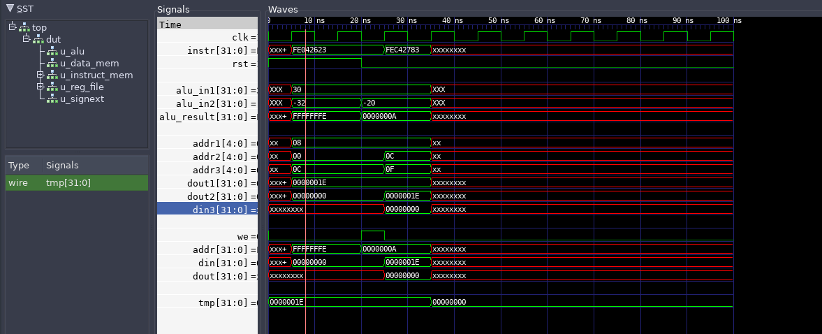
I used machine code from previous post. Hopefully I can complete the simple assembler to generate hex myself. For now, I used the following two instruction:
 fe042623                sw      zero,-20(s0)
 fec42783                lw      a5,-20(s0)
And it works! Kinda!
                  25 Writing ram[0xa]=0x0
                  35 Writing regfile[15]=0x0
and mandatory gtkwave pic

Gotchas Link to heading
Issue 1 iverilog doesn’t play nice with multi-dim arrays(ie memories)
`ifdef SIM
generate
  genvar idx;
  for(idx = 0; idx < 32; idx = idx+1) begin: x
    wire [31:0] tmp;
    assign tmp = mem[idx];
  end
endgenerate
`endif
Issue 2 Reset to control unit as i start the PC at 0, after reset the first instruction is executed twice until the PC changes to next instruction. The solution(Hacky as hell), feed reset to control unit and keep default control signals to prevent regfile or memory write in reset.
[2] RISCV specs